July 2007
NuForce P-9
Preamplifier: Measurements
All preamplifier measurements are performed
independently by BHK Labs. Please click to
learn more about how we test preamplifiers there. All measurement data and graphical
information displayed below are the property of SoundStage! and Schneider
Publishing Inc. Reproduction in any format is not permitted.
- Measurements were made at 120V AC line voltage and on the
left channel unless otherwise noted. Unity gain for instrument loading, balanced, and
unbalanced output is 35 on front-panel display.
- This preamplifier does not invert polarity.
- AC line current draw
- Standby: 0.11A
- Operate: 0.13A
- Input impedance at 1kHz:
- Unbalanced input = 20.7k ohms
- Output impedance at 1kHz:
- Unbalanced output = 95.0 ohms
- Balanced output = 95.0 ohms
- Gain, balanced output, volume at maximum:
- Instrument loading, Lch/Rch = 2.40X, 7.6dB / 2.44X, 7.8dB
- IHF loading, Lch/Rch = 2.37X, 7.5dB / 2.41X, 7.6dB
- Gain, unbalanced output, volume at maximum:
- Instrument loading, Lch/Rch = 2.39X, 7.6dB / 2.43X, 7.7dB
- IHF loading, Lch/Rch = 2.37X, 7.5dB / 2.41X, 7.6dB
- IHF Sensitivity, input volts for standard IHF output of
0.5V, IHF loading:
- Balanced output, Lch/Rch = 211.0mV / 207.5mV
- Unbalanced output, Lch/Rch = 2.11.0mV / 207.5mV
- Output noise versus bandwidth and volume-control position:
- Balanced output, at maximum, Lch | Rch, wideband/A
weighted =
120.0µV / 42.4µV | 68.6µV / 16.0µV
- Balanced output, at unity gain, Lch | Rch, wideband/A
weighted =
163.2µV / 64.2µV | 49.6µV / 7.8µV
- Balanced output, at typical listening level (20dB below
unity gain), Lch | Rch, wideband/A weighted =
163.2µV / 64.2µV | 49.6µV / 7.8µV
- Balanced output, at minimum, Lch | Rch, wideband/A weighted
=
148.6µV / 52.4µV | 44.0µV / 7.1µV
- Unbalanced output, at maximum, Lch | Rch, wideband/A
weighted =
76.7µV / 15.9µV | 69.6µV / 15.6µV
- Balanced output, at unity gain, Lch | Rch, wideband/A
weighted =
87.1µV / 12.5µV | 71.9µV / 12.2µV
- Unbalanced output, at typical listening level (20dB below
unity gain, Lch | Rch, wideband/A weighted =
91.4µV / 8.0µV | 59.8µV / 7.8µV
- Unbalanced output, at minimum, Lch | Rch, wideband/A
weighted =
92.3µV / 7.0µV | 54.8µV / 7.3µV
General
The NuForce P-9 line-level preamplifier is a new product
offering from a company recently well known for its switching power amplifiers.
Chart 1 shows the frequency response in the unbalanced I/O
mode with the volume control set for unity gain for 0.5V input with instrument and IHF
loading. The closest front-panel gain setting for this is 35. In this chart, both channels
are shown. The effect of the IHF loading is essentially negligible and the two channels
are tracking within about 0.2dB at this point on the volume control.
The rise in high-frequency response is suggestive of a peak
beyond 200kHz. Results were the same for the balanced outputs.
In Chart 2, for the gain set to maximum, the very
high-frequency response now rolls off a bit. This change in response happens between the
unity-gain and the maximum-gain settings. For all gain settings down to about –50dB,
the response looks like in Chart 1. Volume-control tracking between channels was mostly
within a few tenths of a dB down to –50dB, except at around –20dB, where the
error was about 1dB. At volume settings greater than 50dB below unity gain, the channel
tracking quickly deteriorated and was off by about 3dB at –60db below unity gain.
Chart 3A shows how total harmonic distortion varies with
input level and frequency for instrument loading in the unbalanced I/O mode. With IHF
loading, the results were the same. This circuit has some increase in distortion at the
higher output levels at 20kHz that would be inconsequential at normal output levels. In
Chart 3B, the results for the balanced output with instrument loading are shown. Again,
there is no real difference with IHF loading. The actual signal distortion is very low in
this design and is dominated by line harmonic and random noise up to about 2V output
– enough to drive most power amplifiers to over 100W output power.
A spectrum of the distortion and noise residual of a 1kHz
test tone at 0.5V output with instrument loading is plotted in Chart 4 for the balanced
output. AC-line hum harmonics here are prominent, and no signal-frequency harmonic
components are visible above the noise floor.
| Chart 1 - Frequency
Response at Unity Gain with IHF and Instrument Loading |
Unbalanced output
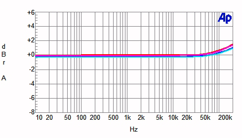
IHF loading
Magenta line = left channel
Red line = right channel
Instrument loading
Red line = left channel
Blue line = right channel
| Chart 2 - Frequency Response as a
Function of Volume Control Setting |
Gain at maximum

Instrument loading
Red line = left channel
Blue line = right channel
| Chart 3 - Distortion
as a Function of Output Voltage and Frequency |
Unbalanced output
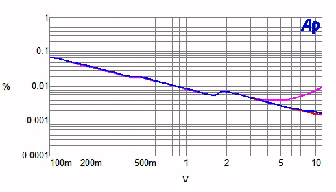
Instrument loading
Red line = 1kHz
Blue line = 20Hz
Magenta line = 20kHz
Balanced output
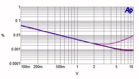
IHF loading
Red line = 1kHz
Blue line = 20Hz
Magenta line = 20kHz
| Chart 4 - Distortion and
Noise Spectrum |
Balanced output

Instrument loading
Red line = spectrum of 1kHz test signal distortion and AC-line harmonics at 0.5V input and
output at unity gain.
|
![[SoundStage!]](../../titles/sslogo3.gif) Home Audio
Home Audio